
Wellhead and manifolds
Fabricated manifolds
Choke and kill, mud standpipe and cement manifolds built to your drawing from our own 4130 pipe, fittings, studded blocks and flanges, welded, tested as an assembly and documented in one data book.
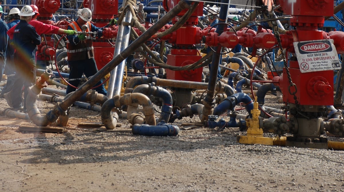
A manifold is an assembly of valves, chokes, fittings and blocks that routes and controls high-pressure flow: a choke and kill manifold controls the well during a kick, a mud standpipe manifold routes mud from the pumps to the standpipes, and a cement manifold connects the cementing unit to the well. We fabricate these manifolds to your drawing from our own AISI 4130 pipe, fittings, studded blocks and flanges, test each one as an assembly, and ship it with a data book of certificates and test records.
Manifold types
| Manifold | What it does | Typical components | Typical rating |
|---|---|---|---|
| Choke and kill | Bleeds and controls well pressure through chokes during well control, and lets mud be pumped in through the kill line | Studded crosses, gate valves, adjustable and positive chokes, gauges, buffer chamber; flanged or clamp hub connections | 5,000 to 15,000 psi |
| Mud standpipe | Routes mud from the pumps to one or two standpipes, with bleed and fill lines | Mud gate valves, tees, long sweeps, goosenecks | 5,000 or 7,500 psi |
| Cement | Connects the cementing unit to the cement head or wellhead | Union-end plug valves, check valves, tees, swivels | 10,000 or 15,000 psi |
Other manifolds, such as test and flowback manifolds, are built to drawing in the same way.
Design references
Choke and kill equipment is specified under API 16C, and the arrangement of choke and kill systems on a rig under API Standard 53. The flanged and studded components follow API 6A, and the piping between them the design code your specification names. The manifold design, its arrangement and its rating are set by your engineer; we build to that design and confirm anything we would change before we cut steel. How bends and targets are chosen for choke lines is in long sweep vs targeted tee.
How a manifold is built
| Step | What happens |
|---|---|
| Drawings | Fabrication drawings, weld map and inspection and test plan from your general arrangement |
| Components | Pipe, fittings, studded blocks and flanges made and tested; bought-in valves received and checked |
| Welding | Welds made to the procedures your specification requires, with post-weld heat treatment where the material and service need it |
| Examination | NDE of welds to the inspection and test plan |
| Assembly | Valves, chokes, gauges and connections fitted; skid mounting if ordered |
| Testing | Hydrostatic test of the assembly at the specified pressure and hold, with chart record; function check of valves |
| Documents | Data book: certificates, weld and NDE records, test charts and the as-built drawing |
For hydrogen sulfide service, every pressure-containing part and weld is made within the hardness limits of NACE MR0175 / ISO 15156, including the heat-affected zones of the welds, and the data book records the hardness survey.
We make these parts to the API 6A and API 16C requirements your order calls up: material, dimensions, tests and marking as specified. We do not hold an API license, so the parts do not carry the API Monogram. If your specification requires monogrammed equipment, the quotation says so plainly.
Ordering
Cement manifold to the attached GA drawing, 2 in FIG 1502 union connections, 15,000 psi CWP, plug valves and check valves as shown, AISI 4130 pipe and fittings, hydrostatic test of the assembly at 22,500 psi with chart, data book, 1 set
Choke and kill manifold to the attached P&ID, 3-1/16 in 10,000 psi, API 6A material class DD, temperature class P, PSL 3, studded crosses and flanged spools in AISI 4130, client-supplied gate valves, one adjustable and one positive choke, data book, 1 set
Frequently asked questions
What do you need to quote a manifold?
A general arrangement drawing or P&ID, the rated working pressure, the service (standard or sour), the material, temperature class and PSL for the API 6A parts, the end connections, the valves and chokes you want or will free-issue, and the test and documentation requirements.
Can you supply the valves and chokes too?
We supply the pipe, fittings, flanges, studded blocks, plug and check valves, chokes and union connections we make. Gate valves and other components from specialist makers can be bought in to your approved vendor list or free-issued by you, and fitted at assembly.
Is the manifold hydrostatically tested as an assembly?
Yes, to the test pressure and hold time your specification sets, with a chart record, and each component is also tested to its own standard before assembly.
Do you mount manifolds on skids?
Yes, to your skid drawing, with lifting points, drip pans or walkways as specified. Lifting points are made to your design and to the load test your lifting procedure requires.